
")

Antennas
Helix Antennen
- Details
|
|
HLX 0810-LHCP
Helix-Antenne Frequenzbereich: 750 bis 1050 MHz Polarisation: linksdrehend nach neuer Definition (LHCP) Gewinn: 11 dBic Halterung: 22 mm Rohr, N-Buchse.
|
| |
HLX 0810-RHCP
Helix-Antenne Frequenzbereich: 750 bis 1050 MHz Polarisation: rechtsdrehend nach neuer Definition (RHCP) Gewinn: 11 dBic Halterung: 22 mm Rohr, N-Buchse.
|
|
|
CLSA 0110 - RHCP
Konisch Logarithmische Spiralantenne Die CLSA 0110 bietet über etwa eine Frequenzdekade zirkulare Polarisation bis in den Mirowellenbereich. Frequenzbereich: 1 - 10 GHz Polarisation: RHCP (right hand circular polarisation)
|
|
|
CLSA 0110 - LHCP
Konisch Logarithmische Spiralantenne Die CLSA 0110 bietet über etwa eine Frequenzdekade zirkulare Polarisation bis in den Mirowellenbereich. Frequenzbereich: 1 - 10 GHz Polarisation: LHCP ( left hand circular polarisation)
|


Feldsonden
- Details
 |
 |
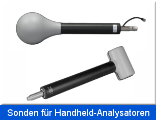
Feldsonden für Handheld-Analysatoren
- Details
| |
FSH3D
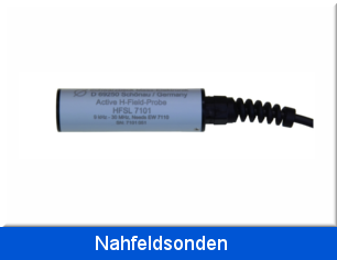
Isotrope H-Feld Antenne für den Rohde und Schwarz Handheld Spektrumanalysator FSH oder das TS-EMF System. 9 kHz - 200 (300) MHz Besonders leichtes und dämpfungsarmes Radom. Außendurchmesser 150 mm
Die Rahmenumschaltung und Spannungsversorgung der Antenne erfolgt über ein mitgeliefertes kurzes Kabel an der Antenne, das an den R&S FSH angeschlossen wird.
|
|
|
NEU
|
FSE3D
Isotrope E-Feld Antenne für Handheld Spektrumanalysatoren. Frequenzbereich: (10) 30 MHz - 3 (3.3) GHz Besonders leichtes und dämpfungsarmes Radom.
Die FSE3D besteht aus drei identischen, aktiven Breitbanddipolen die alle senkrecht aufeinander stehen. Im Anschluss folgt die Umschalt- und Verstärkereinheit, die direkt mit dem Ausgang der FSE3D verbunden ist (N-Stecker) und über den Binderstecker mit Betriebsspannung und Logiksignalen zur Achsenauswahl versorgt wird. Die Belegung des Bindersteckers ist zum Betrieb mit den weit verbreiteten, tragbaren Spektrumanalysatoren FSH 3/6 bzw. FSH 4/8 von Rohde & Schwarz ausgelegt. Zum Schutz vor Umgebungseinflüssen wie Staub oder Spritzwasser ist die FSE3D mit einem HF-transparenten Radom ausgestattet. Aufgrund des geringen Gewichts kann die FSE3D direkt auf den Spektrum Analysator aufgeschraubt werden. Alternativ ist auch ein vom Messgerät räumlich abgesetzter Betrieb möglich, dann kann die FSE3D bequem am 50 mm dicken Schaftrohr gehalten werden (z.B. Schwenkmethode) oder auch am 22 mm Rohr auf einem Stativ oder Mast befestigt werden (Dreh- und Punktrastermethode).
|
|
| |
FSHPH
H-Feld Sonde für Handheld-Analysatoren aller gängigen Hersteller.
Geeignet für:
9 kHz - 300 MHz
Die FSHPH ist eine passive, einachsige H-Feld Sonde für hohe magnetische Feldstärken. Sie eignet sich zur Feldstärkenmessung nach den Personenschutzrichtlinien gemäß BGV-B11, ICNIRP, IEEE C95.1, FCC 96-236 uvm. und ermöglicht dadurch eine genaue Sicherheitsbeurteilung der jeweiligen Umgebung.
|
|
| |
FSHPE
E-Feld Sonde für Handheld-Analysatoren aller gängigen Hersteller.
Geeignet für:
9 kHz - 200 (300) MHz
Die FSHPE ist eine passive, einachsige E-Feld Sonde für hohe Feldstärken. Sie eignet sich zur Feldstärkenmessung nach den Personenschutzrichtlinien gemäß BGV-B11, ICNIRP, IEEE C95.1, FCC 96-236 uvm. und ermöglicht dadurch eine genaue Sicherheitsbeurteilung der jeweiligen Umgebung.
|
|


Breitband Hornantennen
- Details
|
|
 |
 |
 |
Antennen-Impedanzkonverter
- Details
|
|
VHIC 9260
Antennen-Impedanzkonverter nach CISPR 25 9 kHz - 30 (120) MHz. Option ACS 110: Ladegerät ACS 110 für VHIC 9260.
|
|
|
|
CA 9260
Die Antennennachbildung CA 9260 (nach CISPR 25 Anhang B, von 150 kHz bis 6.2 MHz, AAN) dient zur Kalibrierung des Übertragungsmaßes S21 des Impedanzkonverters VHIC 9260.
|
|


Rolling Stock Antennen
- Details
| |
RSAL 5340
3-dimensionale magnetische Rahmenantenne Achszähler - Antenne für Bahnanwendungen - Kompatibilität zwischen Fahrzeugen und Gleisfreimeldesystemen unteren Frequenzbereich nach CLC/TS 50238-3:2010. 10 kHz bis 100 kHz.
|
|
| |
RSAH 5324
3-dimensionale magnetische Rahmenantenne Achszähler - Antenne für Bahnanwendungen - Kompatibilität zwischen Fahrzeugen und Gleisfreimeldesystemen oberer Frequenzbereich nach CLC/TS 50238-3:2010. 100 kHz bis 1.3 MHz.
|
|
| |
RSA COVER
Schmutz- und Wetterschutzhaube zur Aufnahme der Eisenbahn- / Achszähler - Antennen RSAL 5340 oder RSAH 5324 und zur Befestigung am Gleis.
|
|


Faltbikonus oder offene Konuselemente
- Details
|
BBAE 9179
Faltbare Elemente für Störfestigkeit im automotive Bereich optimiert für 1 m Messentfernung Durchmesser maximal 150 cm 20-220 MHz passend für: VHBC 9133, VHBD 9134, VHBD 9134-4. Balun muss ggf. angepasst werden!
|
||
| |
BBFA 9146
BBFA 9146 Faltkonuselemente sind große, offene Konuselemente, deren Öffnungswinkel variabel eingestellt werden kann. Um die Eigenschaften der Antenne im unteren Frequenzbereich zu verbessern, ist es zudem möglich, die Elemente mit Extensions zu verlängern.
Frequenzbereich: 20 - 220 MHz
Länge mit Extensions (Elementverlängerungen): ca. 4 m
|
|
|
FBAB 9177 Faltkonus-Elemente
Die Faltkonus-Elementen FBAB 9177 kombiniert mit einem der folgenden Antennenhalter / Balun VHA 9103 / VHBA 9123 / VHBB 9124 haben ähnliche Eigenschaften wie Antennen mit Bikonuselementen BBA 9106.
(Rundstrahlcharakteristik in der H-Ebene, „8“-er Charakteristik in der E-Ebene, festes Phasenzentrum und einen vergleichbaren Gewinn).
Faltkonus-Elemente lassen sich hingegen platzsparend zusammenfalten und nehmen so weniger Raum bei Transport und Lagerung ein
30 - 300 MHz
|
||
|
FBAL 9178
grosser Faltbikonussatz (Statt BBAL 9136) 20 - 200 MHz
|
||
|
BAOC 9216
Offene Konuselemente 160-1200 MHz (für UBAA 9114/9115)
|
||
| |
BBOC 9217
Offene Konuselemente (30)100-1000 MHz (für UBAA 9114/9115)
|
|


Mastadapter
- Details
| |
AA 9202
Mastadapter für Antennen Mastsystem AM 9144 für Antennen mit 22 mm Rohr 3/8" und 1/4'' Kameragewinde Polarisation beliebig schwenkbar
|
|
|
|
PDG 9211 - Polarisations - Drehgestell
Das Polarisationsdrehgestell PDG 9211 erlaubt eine schnelle und einfache Polarisationsdrehung größerer Hornantennen ohne Höhenversatz durch nur eine Person. Die vierfache Rastmöglichkeit erlaubt ein Einrasten der Antenne in allen 90° Positionen.
Die Antenne wird in der Nähe ihres Schwerpunktes getragen. Das Polarisationsdrehgestell kann auf dem Stativ AM 9144 mit einem 3/8" Kameragewinde befestigt werden.
Optional ist ein pneumatischer Polarisationssteller verfügbar, der eine ferngesteuerte Drehung erlaubt.
|
|
| |
AA 9202 POM
Kunststoffmastadapter zur Minimierung von Reflektionen für alle leichten Antennen mit 22 mm Rohr für AM 9144, 3/8" Kameragewinde Polarisation beliebig schwenkbar
|
|
| |
AA 9203
Mastadapter für alle Antennen mit 22mm Rohr, für AM 9144 3/8'' und 1/4'' Kameragewinde Polarisation und Elevation beliebig schwenkbar
|
|
|
|
RA 9215
Rastadapter RA 9215 für rastenden Wechsel der Polarisation (90° Schritte) für alle Antennen mit 22 mm Rohr und Rastring 3/8'' und 1/4'' Gewinde
|
|
|
|
AA 9205
Orthogonal Schwenkadapter zur Positionierung in 3 orthogonalen Raumrichtungen Anwendung: Bestimmung d. Ersatzfeldstärke
|
|
| |
AA 9209
Antennenadapter zur Halterung der STLP 9128 E, STLP 9128 E special, STLP 9128 D, STLP 9128 D special auf AM 9144. Geometrie für Drehen ohne Höhenversatz und ohne Anstoßen der Elemente am Mast ausgelegt. Antenne wird im Schwerpunkt gehalten.
|
|
| |
AA 9213
Adapter für Antennen mit nur 3/8 Zoll Gewindebohrung. Adapter hat 22 mm Rohr und Rastring z.B. zur Befestigung von BBHA 9170 auf AM 9104.
|
|
|
POSITIONER
Positionierer für SBA 9113 mit 420 NJ bestehend aus: 1 Stück 100 cm Rohr GFK 22 mm mit montiertem AA 9203 sowie einem 3/8 Zoll Gewindestift auf der gegenüberliegenden Seite.
|
||
|
R&S Flange
R&S Flansch für Schwarzbeck Antenne mit 22 mm Rohr.
|
||
| |
RS 9214
Adapter zur Konvertierung des R&S Alu-Flansches zu 22 mm Rohr mit Rastring.
|
|
| |
ETSA 9227
Adapter für leichte Hornantennen diverser Hersteller mit 50 mm Lochkreis auf 22 mm Rohr mit Rastring. Passend für: ETS 3115, EMCO 3115, A-INFO LB-10180, R&S HF 906, R&S HF907 ....
|
|
|
||
| |
KG 9201
Mastadapter (schwenkbar, 90° Vertikal/Horizontalpolarisation für AM 9144, nur für VULP 9118 D/E/F/G sowie VUSLP 9111 E)
|
|
| |
PPS 9208
Pneumatischer Polarisationssteller mit doppeltwirkendem Pneumatikzylinder passend für alle Schwarzbeck Antennen mit 22 mm Rohr auf AM 9144. Pressluftanschluss erforderlich.
|
|
|
SWHA 9204
Schwenkgriff für leichte Antennen für Schwenkmethode
|
||
| |
EA 9207
Adapter für Schwarzbeck Antennen m. 22 mm Rohr auf EMCO Mast.
|
|
|
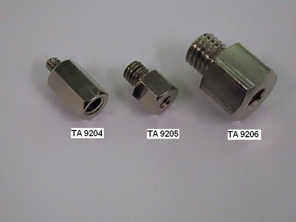
TA 9204
Gewindeadapter-Reduzierstück mit 3/8" Innengewinde und 1/4" Außengewinde Hauptsächlich zur Montage von Amerikanischen Antennen.
|
||
|
TA 9205
Gewindeadapter mit 1/4" Innengewinde und 3/8" Außengewinde (für Kamerastative mit 1/4" Außengewinde, nicht für AM 9144).
|
||
|
TA 9206
Gewindeadapter mit 3/8" Innengewinde und 5/8" Außengewinde (Vermessungstechnik)
|
||


- Details
nicht mehr lieferbar!
Die Gewinn-Normale SGA bestehen aus einem quadratischen Reflektor der Kantenlänge l. Im Abstand von l/4 vor dem Reflektor sind jeweils 2 Halbwellendipole angebracht. Der Isotropgewinn beträgt etwa 9.8 dBi bei der Dimensionierungsfrequenz. Die Dimensionierungsfrequenz kann zwischen 430 MHz und 2.8 GHz angegeben werden. Der 3 dB-Öffnungswinkel beträgt etwa 60 °. Die Normale werden eingesetzt, wenn eine Referenzantenne mit exakt bekanntem Gewinn bei guter Richtwirkung und guter Rückdämpfung benötigt wird.
|
SGA 900
Gewinn-Normale Typ. 9.8 dBi 60° Öffnungswinkel individuell Kalibriert (2 Halbwellendipole vor lambda x lambda Reflektor, EIA / IEC, Dimensionierungsfrequenz ca. 400-2800MHz, paarweise Kalibrierung mit Typ. 0.25 dB Genauigkeit)
|
||
|
SGA 1800
Gewinn-Normale Typ. 9.8 dBi 60° Öffnungswinkel individuell Kalibriert (2 Halbwellendipole vor lambda x lambda Reflektor, EIA / IEC, Dimensionierungsfrequenz ca. 400-2800MHz, paarweise Kalibrierung mit Typ. 0.25 dB Genauigkeit)
|
||
| |
SGA 2450 Gewinn-Normale Typ. 9.8 dBi 60° Öffnungswinkel individuell Kalibriert (2 Halbwellendipole vor lambda x lambda Reflektor, EIA / IEC, Dimensionierungsfrequenz ca. 400-2800MHz, paarweise Kalibrierung mit Typ. 0.25 dB Genauigkeit)
|
|


Monitoring & Drive Test Antennen
- Details
| |
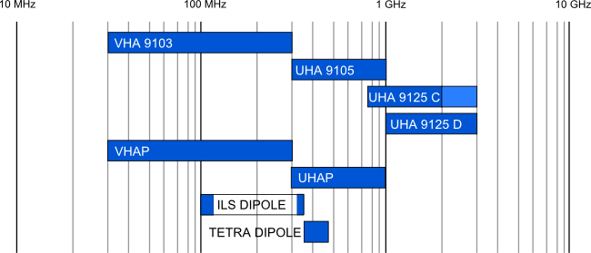
TETRA Dipol
Linear polarrisierter Halbwellendiepol mit 1:1 Übertrager und Festlängen-Elementen
Frequenzbereich: 340 - 480 MHz
Gewinn: typ 1.5 dBi
|
|
|
ILS Dipol
Linear polarisierter Halbwellendipol mit 1:1 Übertrager und Festlängen-
Frequenzbereich: 108 - 118 MHz ( Landekurzsender, localizer, LOC oder LLZ) 320 - 340 MHz ( Gleitwegsender, glideslope, G/S)
Gewinn (isotrop): 1.5 dBi
|
||
|
RSH 113
Die RSH 113 ist ein Kreuzdipol, bestehend aus zwei kapazitiv verkürzten Halbwellendipolen. Durch die Verwendung von Endscheiben kann eine Größenreduktion im Vergleich zum gestreckten Dipol erreicht werden. Die RSH 113 wurde für den Frequenzbereich von 108 MHz bis 118 MHz entwickelt und kann z.B. für Messungen an Instrumenten-Landesystemen (ILS-Localizer) eingesetzt werden. Sie hat Rundstrahlcharakteristik bei horizontaler Polarisation und kann sowohl für Sende- als auch Empfangsanwendungen genutzt werden.
|
||
|
|
RSH 4786
Horizontal polarisierte UHF Rundstrahlantenne für Empfangs- und Sendebetrieb im Mobil- und Stationäreinsatz. Eine typische Anwendung dieser Antenne ist die DVB-Versorgungsmessung (DVB-T) mittels Funkmeßwagen.
Nutzbarer Frequenzbereich: 350 - 1050 MHz
|
|
| |
RSH 2342
Horizontal polarisierte UHF Rundstrahlantenne für Empfangs- und Sendebetrieb im Mobil- und Stationäreinsatz.
Nutzbarer Frequenzbereich: 170 - 350 MHz
|
|
| |
RE 1790
Vertikal polarisierte VHF- UHF Bikonus - Rundempfangsantenne (170) 230 - 1000 (1100) MHz mit Rundstrahlcharakteristik in der H-Ebene.
|
|
| |
RE 4590
Vertikal polarisierte VHF- UHF Bikonus - Rundempfangsantenne (330) 450 - 1000 (1100) MHz mit Rundstrahlcharakteristik in der H-Ebene.
|
|
| |
RS 16
Vertikal polarisierte Mikrowellen Bikonusantenne (0,5) 1 - 6 (8,5) GHz mit Rundstrahlcharakteristik in der H-Ebene.
|
|
| |
RS 0460
Vertikal polarisierte symmetrische Bikonusantenne 0,4 - 6 GHz mit Rundstrahlcharakteristik in der H-Ebene.
|
|
|
RRAH 9286
Der RRAH 9286 ist ein Antennenhalter für Antennen mit 22 mm Rohr zur senkrechten Montage an einem PKW-Dachgepäckträger. Der Antennenhalter ist für alle Standard Dachgepäckträger mit einer max. Querrohr- Abmessung von 44x30 mm geeignet. Der Montage- Abstand ist von 82-92 cm in 2,5 cm Abständen (Mitte-Mitte) einstellbar.
|
||
| |
FT 01 S
Funkmesswagen-Antenne, Basisausführung, zerlegbar 47-860 (1000) MHz
|
|
|
FT 01 UKW
UKW-Zusatzelemente für FT 01 85 - 110 MHz
|
||


Monopol-/Stab-Antennen
- Details
|
|
VAMP 9243
Vertikale aktive Monopolantenne 9kHz - 30 MHz BNC reduziertes Grundrauschen mit Befestigungsmutter für AM 9144 und Akkupack
Options: Opt. GP: Aluminium-Groundplane, 0.6 x 0.6 m Opt. ACS 410: Ladegerät ACS 410 Opt. VT: 20 dB Vorsteckerverteiler zur Erweiterung der maximal messbaren Feldstärke mit Kalibrierdaten Opt. CA 9243: Kalibrieradapter für VAMP 9243
Opt. MIL461F bonding kit: Bonding Kit für VAMP 9243 nach MIL-STD-461F doppelt geschirmtes BNC Kabel ca. 70 cm lang mit Mantelstromsperrferrit mittig, Aluminiumwinkel mit BNC Flanschbuchse doppelseitig.
|
|
|
VPMP 9242
Vertikale passive Monopolantenne 10 - 40 MHz mögliche Monopolstäbe: FBAB 9177, FBAL 9178, BBA 9106, BBAL 9136 (Monopolstab muss extra bestellt werden!)
Option: Opt. GP: Aluminium-Groundplane 0.6 x 0.6 m
|
||
| |
VPMP 9241
Monopol gem. CISPR/D/391/CD (CIS/D/386/CD, CIS/D/388A/CC) passiv 2 N-Buchsen Spannzange für Stab Stab Alugehäuse mit Grundplatte
Option: Opt. TLD 9241: Endscheibe(top loading disc) für VPMP 9241 Durchmesser < 12 cm.
|
|


Dipol Antennen
- Details
Abgestimmte Halbwellen-Dipole zählen schon seit Beginn der Antennentechnik zu den wichtigsten Antennentypen überhaupt. Die Eigenschaften der Halbwellendipole konnten schon sehr früh durch Methoden der analytischen Feldtheorie berechnet werden. Daher werden Halbwellendipole häufig als Referenzantenne eingesetzt. Der ideale (verlustfreie) Halbwellendipol weist stets einen Isotropgewinn von 2.15 dBi und eine Impedanz von 73 Ohm auf. Das Richtdiagramm in der H-Ebene ist kreisförmig (Rundstrahl-Charakteristik), in der E-Ebene "8-förmig", wobei die Maxima senkrecht zur Dipolachse stehen. Der 3 dB-Öffnungswinkel beträgt ca. 78°. Die Impedanz realer Dipole beträgt je nach Schlankheitsgrad der Elemente ca. 60-70 Ohm. In der kommerziellen HF-Messtechnik werden Dipole im Frequenzbereich von 30 MHz bis zu ca. 4 GHz eingesetzt. Dipolelemente sind entweder als Teleskope oder als Festlängenelemente ausgeführt, letzteres insbesondere bei Frequenzen oberhalb von 1 GHz. Die wichtigsten Anwendungen sind Felddämpfungsmessungen und die Bestimmung von ERP (Effektive Strahlungsleistung) bzw. EIRP (Effektive Isotrope Strahlungsleistung).
|
VHA 9103
VHF Halbwellendipol mit 2 Satz Teleskopelementen 30-300 MHz
|
||
| |
UHA 9105
Abstimmbarer UHF-Halbwellendipol 300 - 1000 MHz mit Teleskopelementen
|
|
| |
UHA 9125 C
Abstimmbarer UHF-Halbwellendipol mit EMI-Schleife 0.75 - 2 GHz mit 4 Satz Elementen LE 180, 140, 100, 80 mm
|
|
| |
UHA 9125 D
Abstimmbarer UHF-Halbwellendipol mit EMI-Schleife 1.0 - 3 (4) GHz mit 6 Satz Elementen LE 140, 114, 90, 72, 60, 48 mm
|
|
| |
VHAP
VHF Präzisionsdipole 30-300 MHz 2 Satz Teleskopelemente (VHAP meist paarweise verwendet) CISPR 16-1-5
|
|
|
VHAPA
Kalibrier-Adapter für VHAP-Präzisionsdipole
|
||
|
CCA Koffer für 2 x VHAP oder 2 x UHAP für andere Antennen auf Anfrage
|
||
| |
UHAP
UHF Präzisionsdipole 300-1000 MHz (UHAP meist paarweise verwendet) CISPR 16-1-5
|
|
|
UHAPA
Kalibrier-Adapter für UHAP-Präzisionsdipole
|
||
|
ILS Dipol
Linear polarisierter Halbwellendipol mit 1:1 Übertrager und Festlängen-
Frequenzbereich: 108 - 118 MHz ( Landekurzsender, localizer, LOC oder LLZ) 320 - 340 MHz ( Gleitwegsender, glideslope, G/S) Gewinn (isotrop): 1.5 dBi
|
||
| |
TETRA - DIPOL
Linear polarisierter Halbwellendipol mit 1:1 Übertrager und Festlängen-Elementen für Messungen an TETRA (terrestrical trunked radio) Funknetzen.
Frequenzbereich: 340 - 480 MHz Gewinn: typ 1.5 dBi
|
|


Bikonische Antennen
- Details

Faltbikonus oder offene Konuselemente
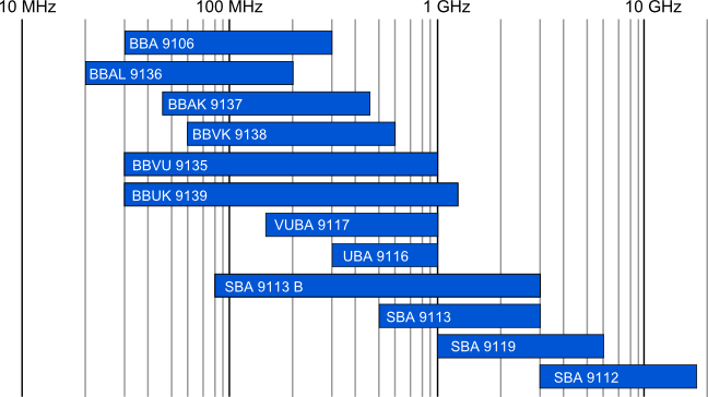
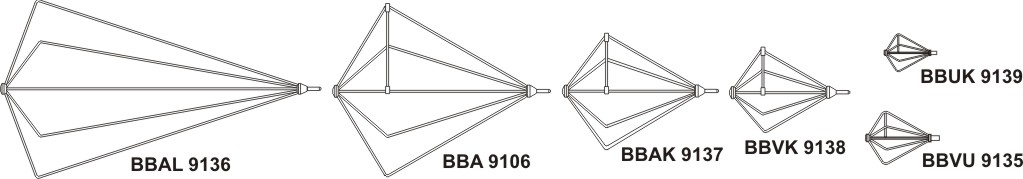
Bikonusantennen haben ähnliche Eigenschaften wie abgestimmte Halbwellendipole (Rundstrahlcharakteristik in der H-Ebene, "8"-er Charakteristik in der E-Ebene, festes Phasenzentrum, vergleichbarer Gewinn) , wobei durch die charakteristische Form der Doppelkonus-Elemente eine recht große Bandbreite erreicht wird. Eine der ersten und weltweit am meisten verbreiteten kommerziellen Bikonusantennen der HF-Messtechnik ist die BBA 9106 mit Balun VHA 9103. Im Laufe der Zeit wurden weitere Bikonusantennen für Anwendungen entwickelt, bei denen neue Frequenzbereiche herunter bis 20 MHz und bis über 18 GHz hinaus erschlossen wurden. Durch die Verwendung von 4:1 Übertragern gelingt eine weitere Vergrößerung der Bandbreite und eine Gewinnsteigerung von ca. 6 dB am unteren
Frequenzbandende. Die Bikonuselemente können innerhalb von wenigen Sekunden kontaktsicher montiert oder demontiert werden, sie werden von Spannzangen
mit Überwurfmuttern gehalten. Ein kleiner Schlüssel aus Isolierstoff zum Öffnen der Spannzangen wird mitgeliefert, er ist direkt am Kopf des Baluns angebunden und so jederzeit greifbar.
Für viele Anwendungen, in denen normalerweise Halbwellendipole eingesetzt werden, kann durch den Einsatz von Bikonusantennen eine beträchtliche Zeitersparnis erzielt werden. Das zeitraubende Abstimmen der Elementlänge auf die halbe Wellenlänge kann entfallen, eine wichtige Grundvorraussetzung für breitbandige
Wobbelmessungen. Bei der Verwendung von abgestimmten Dipolen werden normalerweise Messungen auf diskreten Frequenzen durchgeführt, die Bikonusantenne erlaubt dagegen einen kontinuierlichen Frequenzdurchlauf, bei dem eventuell vorhandene Messplatzanomalien wesentlich zuverlässiger entdeckt werden.
Typische Anwendungen für Bikonusantennen
sind daher:
- Breitband-Empfangsantenne für Emissionsmessungen (20-300 MHz)
- Sendeantenne für Störfestigkeitsprüfungen bei tiefen Frequenzen
- Schirmdämpfungsmessungen
- Bestimmung der Messplatzeigenschaften (z.B. Absorberraum oder Freifeldmessplatz)
- Passive Feldsonde bei Störfestigkeitsprüfungen oder zur
- Bestimmung des Feldstärkeverlaufs (homogene Zone)
Eine Vielzahl von verschiedenen Kombinationen ermöglicht für jeden Anwendungsfall die Auswahl der optimalen Antenne. Für Empfangsanwendungen (Emissionsmessungen) sind die mit "RX" gekennzeichneten Baluns aufgrund ihrer hervorragenden Symmetrie am besten geeignet, für Sendeanwendungen bei hohen Leistungen (Immunitätsprüfung) die mit "TX" markierten Baluns.
BBA 9106 bikonische Elemente kombiniert mit verschiedenen Antennenhaltern / Baluns |
||
|
BBA 9106 + VHA 9103 B BBA 9106 bikonische Elemente mit VHA 9103B Antennenhalter/Balun. 30 - 300 MHz 10 W RX
|
||
| |
BBA 9106 + VHBB 9124 BBA 9106 bikonische Elemente mit VHBB 9124 Antennenhalter/Balun. 30 - 300 MHz 10 W RX
|
|
|
BBA 9106 + HFBA 9122 HFBA 9122 Breitband Balun/Antennenhalter mit BBA 9106 bikonischen Elementen. Speziell für die Messung hoher Feldstärken. (0.1) 0.15 - 300 (500) MHz
|
||
|
BBA 9106 + VHBA 9123 VHBA 9123 Breitband-Balun/Antennenhalter mit BBA 9106 bikonischen Elementen. 30 - 300 MHz TX 100 W
|
||
|
BBA 9106 + VHBC 9133 VHB 9133 Breitband-Balun/Antennenhalter mit BBA 9106 bikonischen Elementen. 30 - 300 MHz TX 1 KW
|
||
|
BBA 9106 + VHBD 9134 VHBD 9134 Breitband-Balun/Antennenhalter mit BBA 9106 bikonischen Elementen. 30 - 200 MHz TX 2.5 KW
|
||
BBAL 9136 bikonische Elemente kombiniert mit verschiedenen Antennenhaltern / Baluns |
||
|
BBAL 9136 + VHA 9103 B BBAL 9136 bikonische Elemente in Kombination mit VHA 9103B Antennenhalter/Balun. 20 - 200 MHz 10 W RX
|
||
| |
BBAL 9136 + VHBB 9124 BBAL 9136 bikonische Elemente in Kombination mit VHBB 9124 Antennenhalter/Balun. 20 - 200 MHz 10 W RX
|
|
|
BBAL 9136 + HFBA 9122 BBAL 9136 bikonische Elemente in Kombination mit HFBA 9122 Breitband-Antennenhalter/Balun. Speziell für die Messung hoher Feldstärken (0.1) 0.15 - 300 (500) MHz 10W
|
||
|
BBAL 9136 + VHBA 9123 BBAL 9136 bikonische Elemente in Kombination mit VHBA 9123 Breitband-Antennenhalter/Balun. 20 - 200 MHz TX 100 W
|
||
|
BBAL 9136 + VHBC 9133 BBAL 9136 bikonische Elemente in Kombination mit VHBC 9133 Breitband Antennenhalter/Balun. 20 - 200 MHz TX 1 KW
|
||
|
BBAL 9136 + VHBD 9134 BBAL 9136 bikonische Elemente in Kombination mit VHBD 9134 Breitband-Antennenhalter/Balun. 20 - 200 MHz TX 2.5 KW
|
||
BBAK 9137 bikonische Elemente kombiniert mit verschiedenen Antennenhaltern / Baluns |
||
|
BBAK 9137 + VHA 9103 B BBAK 9137 bikonische Elemente in Kombination mit VHA 9103B Antennenhalter/Balun. 45 - 450 MHz 10 W RX
|
||
|
BBAK 9137 + HFBA 9122 BBAK 9137 bikonische Elemente in Kombination mit HFBA 9122 Breitband-Antennenhalter/Balun. Speziell für die Messung hoher Feldstärken (0.1) 0.15 - 300 (500) MHz 10W
|
||
| |
BBAK 9137 + VHBB 9124 BBAK 9137 bikonische Elemente in Kombination mit VHBB 9124 Antennenhalter/Balun. 45 - 450 MHz 10 W RX
|
|
BBVK 9138 bikonische Elemente kombiniert mit verschiedenen Antennenhaltern / Baluns |
||
|
BBVK 9138 + VHA 9103 B BBVK 9138 bikonische Elemente in Kombination mit VHA 9103B Antennenhalter/Balun. 60 - 600 MHz 10 W RX
|
||
|
BBVK 9138 + HFBA 9122 BBVK 9138 bikonische Elemente in Kombination mit HFBA 9122 Breitband-Antennenhalter/Balun. (0.1) 0.15 - 300 (500) MHz 10W
|
||
| |
BBVK 9138 + VHBB 9124 BBVK 9138 bikonische Elemente in Kombination mit VHBB 9124 ANtennenhalter/Balun 60 - 600 MHz 10 W RX
|
|
BBVU 9135 bikonische Elemente kombiniert mit verschiedenen Antennenhaltern / Baluns |
||
| |
BBVU 9135 + UBAA 9114 BBVU 9135 bikonische Elemente in Kombination mit UBAA 9114 Antennenhalter/Balun. verlustarm 30 - 1000 MHZ 5 W RX
|
|
|
BBVU 9135 + UBAA 9115 BBVU 9135 bikonische Elemente in Kombination mit UBAA 9115 Antennenhalter/Balun hochsymmetrisch 30 - 1000 MHZ 5 W RX
|
||
BBUK 9139 bikonische Elemente kombiniert mit verschiedenen Antennenhaltern / Baluns |
||
|
BBUK 9139 + UBAA 9114 BBUK 9139 bikonische Elemente in Kombination mit UBAA 9114 Antennenhalter/Balun. verlustarm 30 - 1200 MHZ 5 W RX
|
||
|
BBUK 9139 + UBAA 9115 BBUK 9139 bikonische Elemente in Kombination mit UBAA 9115 Antennenhalter/Balun. hochsymmetrisch 30 - 1200 MHZ 5 W RX
|
||
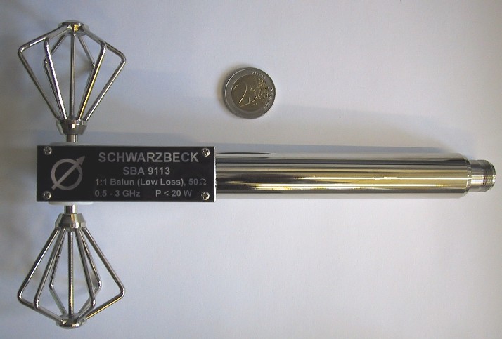
|
SBA 9113 B Kleine Bikonusantenne 80 MHz - 3 GHz zum Messen der Harmonischen nach IEC61000-4-3.
|
||
| |
SBA 9113 Mikrowellen-Bikonusantenne 0.5 - 3 GHz 20 W CIS/A/648/CDV CISPR16-1-4:2007-02 Ed. 2.0 Site evaluation above 1 GHz ( SiteVSWR )
|
|
| |
420 NJ Elemente für Störfestigkeit gegen Handy Transmitter für den Standard RI115 von Ford (Ford EMC CS 2009) für SBA 9113 oder SBA 9113 mini version.
Option: Opt: Spacer 50 Abstandhalter aus Polystyrol für 420 NJ Elemente. Prüfabstand 50 mm..
|
|
| |
SBA 9112 Mikrowellen - Bikonusantenne (1) 3 - 18 GHz 10 W mit Transportkoffer CISPR16-1-4:2007-02 Ed. 2.0 Die Mikrowellen - Bikonusantenne SBA 9112 ist konform zu CISPR 16-1-4 site validation above 1 GHz. (Site-VSWR)
|
|
| |
SBA 9119 Mikrowellen-Bikonusantenne 1 - 6 GHz 20 W CIS/A/648/CDV CISPR 16-1-4 Site validation above 1 GHz mit Transportkoffer
|
|
| |
UBA 9116 Bikonische UHF Breitbandantenne (160) 300 -1000 (1100) MHz
|
|
| |
VUBA 9117 Bikonische VHF-UHF Breitbandantenne (30) 150 -1000 MHz
|
|
|
RS 16 Vertical polarisierte Mikrowellen Bikonusantenne mit Rundstrahlcharakteristik in der H-Ebene. (0.5) 1 - 6 (8.5) GHz
|
||
| |
RE 1790 Vertical polarisierte Mikrowellen-Bikonusantenne mit Rundstrahlcharakteristik in der H-Ebene. (170) 230 - 1000 (1100) MHz
|
|
| |
RE 4590 Vertical polarisierte Mikrowellen-Bikonusantenne mit Rundstrahlcharakteristik in der H-Ebene. (330) 450 - 1000 (1100) MHz
|
|
| |
RS 0460 Vertical polarisierte Mikrowellen-Bikonusantenne mit Rundstrahlcharakteristik in der H-Ebene. 0.4 - 6 GHz
|
|


Antennenhalter / Baluns
- Details
| |
VHA 9103 B
Antennenhalter / Balun 1:1 ohne Teleskopelemente (z.B. zur Benutzung mit bikonischen Elementen BBA 9106, BBAL 9136, BBAK 9137, BBVK 9138, FBAB 9177)
|
|
|
HFBA 9122
Passiver Antennenhalter Speziell für hohe Feldstärken bis 3000V/m 150kHz bis 300(500) MHz. BBAL 9136, BBA 9106, BBAK 9137, BBVK 9138, BBVU 9135 oder BBUK 9139 Elemente erforderlich.
|
||
|
VHBA 9123
Antennenhalter / Balun für Bikon. Breitband Antennen (z.B. BBA 9106, BBAL 9136, BBAK 9137, FBAL 9178 ) 50:200 Ohm verbessertes Wandlungsmaß unter 50 MHz, auch für Immunitätsprüfungen 100 W
|
||
| |
VHBB 9124
Antennenhalter / Balun 50:200 Ohm hohe Symmetrie 25-300 MHz 10 W verbesserter Antennenfaktor im unteren Frequenzbereich für BBA 9106, BBAL 9136, BBAK 9137, BBVK 9138, FBAB 9177, FBAL 9178.
|
|
| |
VHBC 9133
Antennenhalter / Balun 50:200 Ohm 1 kW 20 - 300 MHz für Bikonus- oder Faltbikonuselemente BBA 9106, BBAL 9136, BBFA 9146, FBAB 9177 ,FBAL 9178, BBAE 9179
|
|
| |
VHBD 9134
Hochleistungs-Antennenhalter / Balun
2.5 kW 50:200 Ohm 20 - 200 MHz
für Bikonus- oder Faltbikonuselemente BBFA 9146 N-Buchse Option 7/16: 7/16 Buchse
|
|
| |
VHBD 9134-4
4 kW Hochleistungs-Antennenhalter / Balun mit 7/16 Buchse 50:200 Ohm für BBAL 9136 oder BBFA 9146 20 - 200 MHz
|
|
|
NEU
|
VHBD 9134-10
10 kW Hochleistungs-Antennenhalter / Balun mit 13/30 Buchse 50:200 Ohm für TRI 0630, BBA 9106, BBAL 9136 oder BBFA 9146 20 - 280 MHz
|
|
| |
UBAA 9114
Breitband-Antennenhalter / Balun 4:1 30 - 1000 MHz verlustarm 5W BBVU 9135, BBUK 9139, BAOC 9216 oder BBOC 9217 - Elemente erforderlich
|
|
| |
UBAA 9115
Breitband-Antennenhalter / Balun 4:1 30 -1000 MHz hochsymmetrisch 5W BBVU 9135, BBUK 9139, BAOC 9216 oder BBOC 9217-Elemente erforderlich
|
|


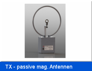
Passive magnetische Rahmenantennen (TX)
- Details
![]() Übersicht passive magnetische Antennen, TX-Loop Antennas
Übersicht passive magnetische Antennen, TX-Loop Antennas
|
HFRA 1356
Die HFRA 1356 ist eine auf Resonanz abgestimmte passive Rahmenantenne. Die Antenne ist zur effizienten Erzeugung definierter Magnetfelder bei 13.56 MHz mit ( vorgesehen, zum Beispiel NFC wird in den Standards ISO 18092, ECMA 340, ETSI TS
Bandbreite: typ. 350 kHz Durchmesser: 250 mm 2 Windungen BNC - Anschlüsse 16 W
|
||||||||||||||||||||||||||||||||||||||
| |
HFRA SF02G
Abstimmbare magnetische Rahmenantenne zur Erzeugung extrem hoher Magnetfeldstärken im Bereich 10 kHz bis 30 MHz nach VG95373-13:2008-11 und VG95373-23:2008-11. Mit Sensorrahmen HFRAE 5163 und Steuerkabel.
|
|||||||||||||||||||||||||||||||||||||
|
HFRA 5146
Runder Senderahmen DC-200 kHz und 15 MHz Durchmesser: 300 mm N-Buchse
|
||||||||||||||||||||||||||||||||||||||
|
HFRA 5148
Runder Senderahmen Durchmesser 180 mm 1 Windung
|
||||||||||||||||||||||||||||||||||||||
|
HFRA 5149
Runder Senderahmen 9 kHz - 30 MHz Durchmesser 500 mm inkl. 50 Ohm Abschluss 20 Watt N-Buchsen
|
||||||||||||||||||||||||||||||||||||||
|
HFRA 5152
Runder, geschirmter Senderahmen Durchmesser 250 mm DC-3 MHz
|
||||||||||||||||||||||||||||||||||||||
| |
HFRA 5153
Runder, geschirmter Senderahmen Durchmesser 180 mm 0-20 (30) MHz 5W
|
|||||||||||||||||||||||||||||||||||||
|
HFRA 5154
Runder, geschirmter Senderahmen Durchmesser 100 mm 0.1-30 MHz 0.5W Übertrager 50 Ohm
|
||||||||||||||||||||||||||||||||||||||
| |
HFRA 5155
Die HFRA 5155 - Rahmenantenne für magnetische Felder ist zur Erzeugung von kleinen bis mittleren Magnetfeldstärken im Frequenzbereich 100 kHz - 300 MHz einsetzbar. Sie besteht aus einer einzigen, geschirmten Windung mit einem Durchmesser von 50 mm.
|
|||||||||||||||||||||||||||||||||||||
| |
HFRA 5156
Runder, geschirmter Senderahmen Durchmesser 50 mm 0-5 MHz 2W 10 Windungen
|
|||||||||||||||||||||||||||||||||||||
| |
HFRA 5157
Runder, geschirmter Senderahmen Durchmesser 100 mm 0-20 (30) MHz 5 W 2 Windungen
|
|||||||||||||||||||||||||||||||||||||
|
HFRA 5158
Runder, geschirmter Senderahmen Durchmesser 180 mm 0-2 MHz 5W 10 Windungen
|
||||||||||||||||||||||||||||||||||||||
| |
HFRA 5159
Runder, geschirmter Senderahmen Durchmesser 250 mm 0-400 kHz 5 W
|
|||||||||||||||||||||||||||||||||||||
|
NEU
|
HFRA 5164
Runder, geschirmter Senderahmen Durchmesser 100 mm 0.01 - 120 MHz 3 Windungen
Empfohlenes Zubehör:
|
|||||||||||||||||||||||||||||||||||||
|
HFRA 5170
Kalibrierrahmen 3 W Durchmesser 100 mm 0-30 MHz 1 Wdg. 250 Ohm
|
||||||||||||||||||||||||||||||||||||||


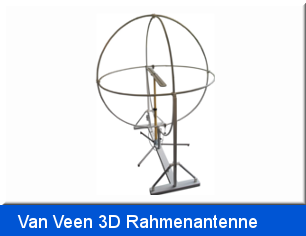
3-Dimensionale Van Veen Rahmenantenne CISPR 15
- Details
| |
HXYZ 9170
Loop Antenna System ( LAS ) 3-dimensionale Rahmenantenne (Van Veen) Durchmesser: 2 m gem. EN 55015 ohne Sockel
|
|
| |
HXYZ 9170 Sockel
Sockel und Befestigung für HXYZ 9170 Rahmenantenne (Van Veen)
|
|
| |
HXYZ 9170 Umschaltbox
Koaxialumschalter 3 in 1 manuell / fernsteuerbar von FMLK / FCKL mit Kabelsatz (3 x BNC mit Mantelstromsperren)
|
|
| |
HXYZ 9170 RS USER Adapter
Der HXYZ 9170 – RS USER Adapter dient zum Anschluss eines R&S Gerätes mit 25poliger User- Schnittstelle (z.B. ESPI, ZVR, ESCI, ESCS, FSB.) an die HXYZ 9170 Umschaltbox.
|
|
| |
HXYZ 9170 RS AUX Adapter
Der HXYZ 9170 – RS AUX Adapter dient zum Anschluss eines R&S Gerätes mit 9poliger AUX Schnittstelle (z.B. ESL und ESR.) an die HXYZ 9170 Umschaltbox.
|
|
| |
HFCD 9171
Kalibrierbalun / Dipol für HXYZ 9170 Empfehlung: Zubehör: Antennen Mast AM 9144
|
|
| |
CDA 9271
Adapter zur Befestigung von HFCD 9171 auf Antennen Mast AM 9144, Gewindebohrungen 3/8 Zoll.
|
|
| |
HXYZ 9170 3m
Loop Antenna System ( LAS ) 3-dimensionale Rahmenantenne (Van Veen) Durchmesser 3 m gem. EN 55015
|
|


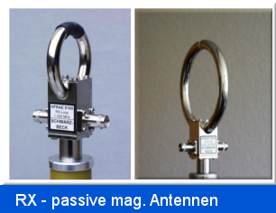
Passive magnetische Rahmenantennen (RX)
- Details
![]() Übersicht passive magnetische Rahmenantenne, RX-Loop Antennen
Übersicht passive magnetische Rahmenantenne, RX-Loop Antennen
| |
HFRAE 5160
VHF - UHF Empfangsrahmen rund Durchmesser 50 mm 2-300MHz Übertrager 50 Ohm
|
|
| |
HFRAE 5161
HF Empfangsrahmen Durchmesser 100mm 70 kHz - 120 MHz 1 Windung Übertrager 50 Ohm
|
|
| |
HFRAE 5162
HF Empfangsrahmen Durchmesser 250mm 50 kHz - 30 MHz 1 Windung Übertrager 50 Ohm
|
|
| |
HFRAE 5163
Passiver magnetischer Empfangsrahmen 9 kHz - 300 MHz 1 Windung Übertrager Durchmesser 50 mm
|
|
|
NEU |
HFRA 5164
Passiver magnetischer Rahmenantenne 0.01 - 120 MHz 3 Windungen Durchmesser 100 mm
Empfohlenes Zubehör:
|
|


Magnetfeld Antennen
- Details
|
|
|
|
|
|
|
|
|
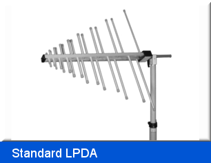
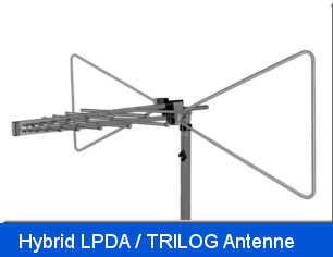
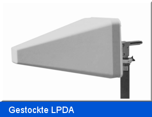
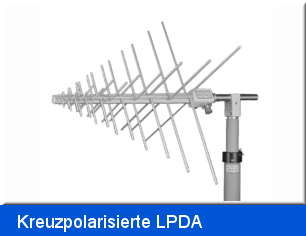
Logarithmisch - periodische Breitbandantennen
- Details
 |
 |
 |
 |
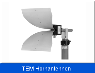
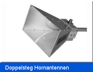
Dual polarisierte Breitband Doppelsteg-Hornantenne
- Details
|
NEU |
CTIA 0710
Dual polarisierte Breitband Doppelsteg-Hornantenne 0.7 - 10 GHz SMA-Buchse
|
|
| |
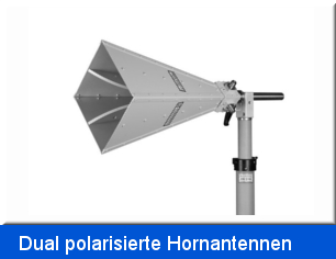
BBHX 9120 E
Dual polarisierte Breitband Doppelsteg-Hornantenne 0.4 - 10 GHz N-Buchse
|
|
| |
BBHX 9120 LF
Dual polarisierte Breitband Doppelsteg-Hornantenne (0.8) 1 - 8 (10.5) GHz N-Buchse
|
|


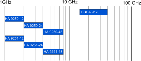
Standard Gain Horn Antennen
- Details
|
BBHA 9170
Breitband Hornantenne 15 - 26.5 (40) GHz SMA-kompatible Buchse
|
||
|
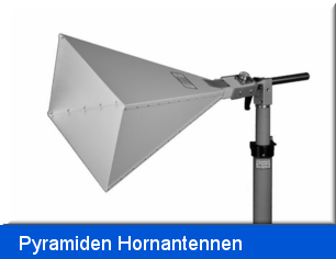
HA 9250-12
Pyramiden Hornantenne 1 - 2 GHz 7/16-Buchse 20 dBi optimiert für Fernfeldgewinn
|
||
| |
HA 9250-24
Pyramiden Hornantenne 2 - 4 GHz 7/16-Buchse 20 dBi optimiert für Fernfeldgewinn
|
|
| |
HA 9250-48
Pyramiden Hornantenne 4 - 8 GHz N oder 7/16-Buchse 20 dBi optimiert für Fernfeldgewinn
|
|
| |
HA 9251-12
Pyramiden Hornantenne 1 – 2 GHz Fernfeldgewinn 19-22 dBi 7/16 Buchse optimiert für 1 m Gewinn.
|
|
|
HA 9251-24
Pyramiden Hornantenne 2 - 4 GHz 7/16-Buchse 18 dBi optimiert für den Gewinn in 1 m Messentfernung
|
||
| |
HA 9251-48
Pyramiden Hornantenne 4 - 8 GHz N oder 7/16-Buchse 19 dBi optimiert für den Gewinn in 1 m Messentfernung
|
|


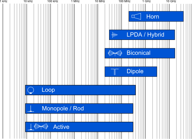
Antennen
- Details
Frequenzübersicht
Aktive Antennen
- Details
| |
EFS 9218
Aktive Bikonusantenne mit eingebautem Akku 9 kHz-300 MHz 12 µV/m ... 65 V/m konst. Wandlungsmaß: typ.: 46 dB/m bzw. mit eingeschaltetem Zusatzvorverstärker AF = 20 dB/m.
Optionen: Opt. ACS 410: ACS 410 Ladegerät für EFS9218
|
|
|
EFS 9219
Aktiver Antennehalter / Balun 9kHz - 30 MHz 1 µV/m ... 3 V/m BBUK 9139 Bikonus-Elemente erforderlich
Optionen: Opt. Rohr: Halterungsrohr mit Mantelstromsperren Opt. ACS 410: ASC 410 Ladegerät für EFS9219
|
||
|
|
VAMP 9243
Vertikale aktive Monopolantenne 9kHz - 30 MHz BNC reduziertes Grundrauschen mit Befestigungsmutter für AM 9144 und Akkupack
Optionen: Opt. GP: Aluminium-Groundplane, 0.6 x 0.6 m Opt. ACS 410: Ladegerät ACS 410 Opt. VT: 20 dB Vorsteckerverteiler zur Erweiterung der maximal messbaren Feldstärke mit Kalibrierdaten Opt. CA 9243: Kalibrieradapter für VAMP9243
Opt. MIL461F bonding kit: Bonding Kit für VAMP 9243 nach MIL-STD-461F doppelt geschirmtes BNC Kabel ca. 70 cm lang mit Mantelstromsperrferrit mittig, Aluminiumwinkel mit BNC Flanschbuchse doppelseitig.
|
|

![[Foto]](/Bilder/9243vorsteckteiler.jpg)